ENGINEERING STUDY
For the
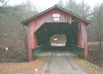
HUTCHINS COVERED BRIDGE
Bridge No. 34
World Guide No. 45-06-02
Town Highway 27
Montgomery, VT
Prepared by: HTA Consulting Engineers, Burlington, Vt.
Prepared for: Vermont Agency of Transportation
The Town of Fairfield, Vt.
July 2006 Revised August 4, 2006
TABLE OF CONTENTS
1. EXECUTIVE SUMMARY
Hoyle, Tanner & Associates, Inc. (HTA) has been assigned, through a retainer contract with the Vermont Agency of Transportation (VTrans), the task of preparing an Engineering Study for the rehabilitation of the Hutchins Covered Bridge. The project's Priority of Uses as defined by the Historic Covered Bridge Preservation plan is "Special Use on Roads" if a six (6) ton live load is pursued and "Limited Use on Roads" if a twenty (20) ton live load is pursued.
The Hutchins Covered Bridge was inspected and load rated to determine it's current condition. Our rating assumes replacement of deteriorated bridge members. It was determined that at the inventory stress limit the existing trusses have a live load capacity of approximately H7.8 (7.8 tons), the floor beams have a capacity of H4.2 (4.2 tons), and the deck has a capacity of H7.2 (7.2 tons).
Additional items are discussed in this report and recommended for the bridge include a temporary detour bridge, utilization of a Class 4 Town Highway as a detour, new siding; substructure repairs, replacement of deteriorated bridge members; fire protection, bridge approach railing, new backwalls; and realignment of the trusses. The total estimated cost of all recommended work items utilizing a temporary detour bridge and six (6) ton live load limit is approximately $578,025.00 including contingencies. The total estimated cost of all recommended work items utilizing a temporary detour bridge and twenty (20) ton live load limit is approximately $777,525.00 including contingencies.
2. INTRODUCTION
HTA has been assigned, through a retainer contract with VTrans, the task of preparing an Engineering Study for the rehabilitation of the Hutchins Covered Bridge. On November 30, 2005 an Inspection Team from HTA visited the bridge to perform field observations and gather field data for this Engineering Study. An archeologist from Hartgen Archeological Associates, Inc. (HAA) visited the site on April 5, 2006 to assess the potential of encountering National Register listed or eligible sites which may be effected by the project.
3. BACKGROUND
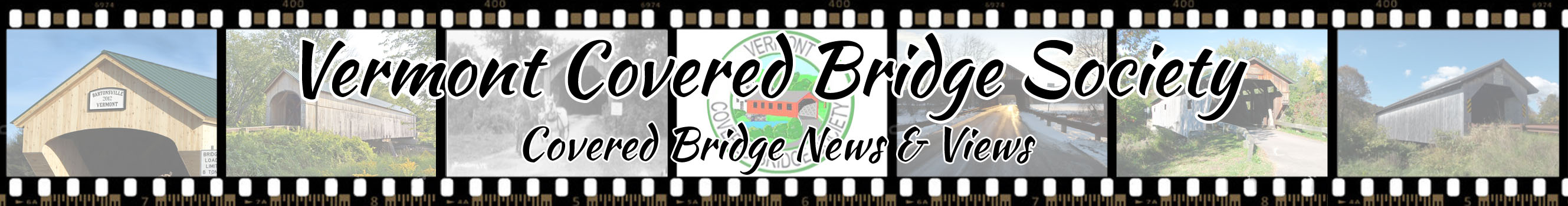
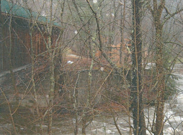
The Hutchins Covered Bridge is located in the Town of Montgomery, Vermont and was built in about 1883 by Sheldon and Savannah Jewett of Montgomery. The bridge's seventy-six (76') foot single span timber superstructure utilizes Town Lattice trusses spaced at 17'-10" on-center (see Appendix C for existing and portal sections and plan view). The bridge runs east to west and crosses over the South Branch of the Trout River on Town Highway No. 27. It is supported by abutments originally constructed out of large stones. The east abutment has been encased with concrete. The west abutment is constructed from dry laid stones and abuts the former Hutchins Mill foundation which serves as the northwest wingwall. The bridge is open to traffic and is on the National Register of Historic Places.
4. FIELD OBSERVATIONS
On November 30, 2005 an inspection team from HT A visited the bridge to perform in depth field measurements and gather field data for this Engineering Study. Mr. Scott Perry representing the Town of Montgomery and Mr. John Weaver representing VTrans were also on site in the morning to discuss the project.
5. WOOD SPECIES IDENTIFICATION
Four (4) small wood samples were removed from the bridge for the purpose of species identification. The samples were taken from deteriorated members that will most likely be replaced during the course of the bridge rehabilitation.
The samples were forwarded Doug Gardner, Ph.D., a professor of Wood Science and Technology, at the University of Maine at Orono for identification. From analysis, it was determined that the deck and the truss chord samples were Eastern Hemlock and the lattice sample is Spruce. The trunnel sample was determined to be hard maple which is somewhat unusual; oak is more typically utilized for trunnels. This species evaluation is consistent with historical records that indicate native wood was used during construction. A copy of Dr. Gardner's report is included as Appendix A.
6. HYDRAULICS
The bridge crosses over the South Branch of the Trout River which runs roughly north to south at the bridge site. At the time of our inspection there was approximately 20-feet of vertical clearance above the water level to the lower chord bottom face elevation.
The VTrans Hydraulics Unit completed a preliminary hydraulic study dated May 25, 2005. The conclusion of the study was that both there is approximately 11' of freeboard over Q100 so hydraulic capacity is not an issue at the site. Scour Analysis was not performed since the abutments are founded on ledge.
7. STRUCTURAL ANALYSIS / REPLACEMENT RECOMMENDATIONS
A structural analysis was performed of all key members of the bridge superstructure. The Service Load (Allowable Stress) design method was used for all members as required by the VTRANS Structures Manual (Chapter 22, Section 22.1). Allowable stress values for wood members were obtained from the 2005 National Design Specification for Wood Construction and Supplement. The wood species used in the superstructure was identified through testing (see Section 5). The grade assigned to each member was based on a visual examination of knots, checks and the growth rate characteristics of the wood. All superstructure members are wood unless noted otherwise.
The condition of each member is detailed in the following sections. In addition, initial recommendations for repair of replacement are made which must be reviewed by the Historic Covered Bridge Committee (HCBC) to assess the structural and historical issues. We have also identified in the recommendations for Sections 7.1 through 7.5 the priority treatment numbers from the Historic Bridge Preservation Plan to aid in review.
It should be noted that not all members to be replaced can be identified based on our inspection due to inaccessible areas (outside face of bottom chord, etc.). The contract documents and estimate of cost in this study include an additional amount of conditional replacement where appropriate to determine an appropriate budget for the project.
1. Roof Framing
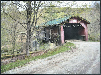
Description: The roof framing consists of a new standing seam metal roof installed in 2002 and attached to 7/8" thick roof boards. The roof boards are supported by 3" x 5" rafters spaced at 2'-0" on center. The rafters are largely supported on the top chord of the trusses, while some rafters frame into the crossbeams. The roof framing also includes a 6½" x 9" ridge beam and 6" x 6" support post supported on the cross beam. 4" x 4" braces span between the cross beam and support post. The rafter and roof board wood species is Eastern Hemlock for analysis and they have been assigned a grading of Select Structural.
The roof framing is in good condition. A section of roof rafters and roof boards were replaced in 2002 when the new standing seam metal roof was installed. The members were replaced due to a large leak in the roof which also severely damaged the trusses. See Section 7.3.
Analysis: The roof rafters were analyzed for dead load and a ground snow load of 50 PSF (33.3 PSF roof applied) per the 2005 Vermont Fire and Building Safety Code snow load and the 2006 International Building Code. The rafters and roof boards were found to be adequate for the applied dead and snow loading.
Recommendations: The metal roof is in good condition having been installed in 2002 and should be retained. Replacement of selected roof boards and rafters was also completed in 2002. We did not note any recent damage to the roof boards or rafters and therefore are not recommending any replacement of these members. We also are not recommending any replacement at the ridge beam support post and braces.
Roof Framing and Supports
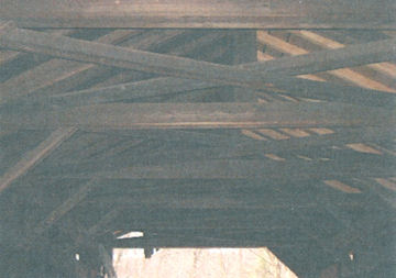
2. Lateral Bracinq
Description: The top lateral bracing consists of 4" x 4" knee braces, 7½" x 7½" crossbeams at 8'-0" on center bearing on top of the rafter support beam and 4" x 4" cross bracing between the cross beams. The 4"x4" knee braces bear on chord 2 with a nailed connection.
The lateral bracing in the bridge is in fair to good condition. The bridge trusses are racked between 3" and 5" depending upon the location. The racking of the bridge has broken the ends of two (2) crossbeams at the northeast corner of the bridge and loosened or cracked several knee braces.
Analysis: The existing top lateral bracing is adequate to resist code required wind and snow loads.
Recommendations: Based on the condition of the upper lateral bracing we recommend the following repairs, replacements or additions:
- Replace two (2) crossbeams. (Priority Treatment No.2)
- Repair splits at the bearing of four (4) crossbeams. (Priority Treatment No.1)
- Replace two (2) knee braces. (Priority Treatment No.2)
- Install four (4) knee braces where missing. (Priority Treatment No.2)
- Install a lag bolt at top lateral bracing intersection.
- Install a lag bolt at the base of all knee braces.
We have assumed that local (northeast) wood species will be used for the members above. It is important to note that they may not be readily available for the cross beams due to the size, length and grade needed.
Upper Lateral Bracing
3. Trusses
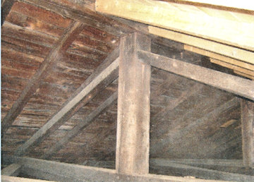
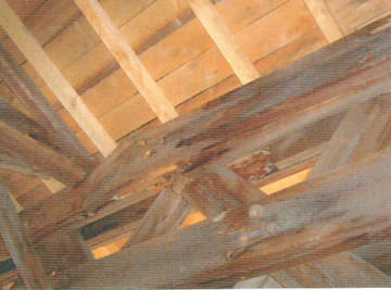
Description: The bridge utilizes Town Lattice trusses with members in very poor to good condition. The chords were identified as a Eastern Hemlock species with a grade of select structural assigned for analysis. The lattice members were identified as a spruce species with a grade of select structural assigned for analysis. Steel beams have been added inside of each truss to help support the bridge due to the poor condition of the truss upper chords.
The trusses are generally in good condition with several locations in the south truss in very poor condition. In these locations, long term leaking of the roof has caused extensive rot with all four (4) chord members broken in one (1) location in the top chord of the south truss. The trusses also exhibit 3" to 5" rack to the south. The camber (or sag) of the bridge was not measured due to the installation of steel beams in the bridge which are supporting it.
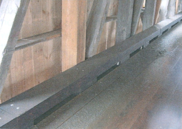
The trusses bear on wood sleeper beams, the size and length of which vary at each bearing. There are no concrete backwalls at the ends of the chords and extensive rot was noted in these locations. We have assumed for this study that all four (4) pieces of chord 4 at the ends of the trusses will be replaced. We will investigate this assumption further during the design of the project with a goal to retain as much material as possible.
Analysis: The trusses were analyzed to determine their current live load capacity. A 3-D, full bridge computer model was utilized for our analysis. Full dead and live loads were applied and compared to inventory stress levels and full dead, live and snow loads were applied and compared to the higher operating stress level. The live load capacity of the trusses was found to be H7.8 (7.8 tons) at inventory and H8.0 (8.0 tons) at operating both ratings are controlled by lattice to chord trunnel capacity. This rating assumes that a total of eight (8) connections at the end of the bridge are strengthened.
Due to the location of the bridge on a dead end road, we have evaluated two (2) live load capacities of the bridge; six (6) tons and twenty (20) tons. A six (6) ton live load capacity would require no member replacement for strength considerations. A twenty (20) live load would require installation of steel or wood stringers beneath the floorbeams and installation of new floorbeams and decking. This approach was used in the Union Village Covered Bridge in Thetford, VT where four (4) glulam stringers were installed beneath the bridge on new abutments and new glulam floorbeams and decking were also added.
Recommendations: Due to the stresses in the trusses and difficulty in obtaining local species, select structural Douglas Fir or Southern Pine is proposed for replacement members in the trusses.
The following recommendations are made for the trusses assuming a six (6) ton live load limit:
- Replace selected lattice members (22 total). (Priority Treatment No.2)
- Replace selected chord members (28 pieces at 28' each, approximately). (Priority Treatment No.2)
- Repair split ends of lattice with epoxy and lag screws (14 total). (Priority Treatment No.1)
The following changes would be required for a twenty (20) ton load rating:
- Replace the deck with a new glulam deck. (Priority Treatment No.2)
- Replace the floorbeams with new glulam floorbeams. (Priority Treatment No.2)
- Install new concrete abutments in front of the existing abutments. (Priority Treatment No.2)
- Installation of new longitudinal glulam stringers. (Priority Treatment No.4)
- Upgrade truss connections as required.
Rack of Trusses (East Portal Shown)
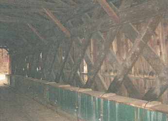
South Truss Elevation
Rot in Top Chord
4. Floor Beams. Strinqers and Deckinq
Description: The existing floor framing consists of a 3" thick plank deck with 2" thick runners supported by floorbeams spaced at approximately 2'-0" on center that are either 7¼" x 9" or 7¼' x 10¼' in size. The decking was identified through testing as an Eastern Hemlock species and the floorbeams were assumed to be the same species. A grade of select structural No. 1 was assigned for analysis. The deck and floorbeams are in fair to good condition with some rot in the deck and large knots and splits in the floorbeams.
Analysis: The existing floor beams and decking were analyzed to determine their live load capacity. The deck capacity was determined to be H7.2 (7.2 tons) assuming a No.1 grade. The floorbeam capacity was determined to be H4.2 (4.2 tons) for a NO.1 grade at inventory and H5.9 (5.9 tons) at operating. If the grade of the floorbeams is assumed to be select structural, the capacity is only increased to H5.3 (5.3 tons) at inventory and H7.3 (7.3 tons) at operating. Based upon a visual evaluation of the floorbeams, we believe the No. 1 grade of the floorbeams should be used due to the large number of edge knots, wane and splits in the existing members.
Recommendations: Based upon the condition of the deck and floorbeams and an H6.0 (6.0 ton) live load goal, we recommend complete replacement of the floorbeams and decking with new sawn members of approximately the same size. The species of the new members would be Douglas Fir or Southern Pine to meet the H6.0 (6.0 ton) live load requirement. If H20.0 (20.0 ton) live load capacity is required, glulam decking and floorbeams would be required as discussed above.
In addition, we recommend that a new wood curb be added to the bridge to help keep vehicles from impacting the trusses and knee braces. This curb has previously been used by VTrans on the Union Covered Bridge in Thetford, the Comstock Covered Bridge in Montgomery and the Greenbanks Hollow Covered Bridge in Danville.
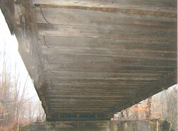
Floor Framing
Proposed Bridge Curb
5. Abutments
Description: The east abutment and wingwalls were most likely originally constructed out of large stones at some unknown date and were encased in concrete. The abutment and wingwalls are in good condition with some cracking and minor spalling noted. There does not appear to be a concrete or stone backwall and no weepholes were noted.
The west abutment and wingwalls are constructed of dry laid stone. The abutment is founded on ledge while the wingwall foundation is unknown. The abutment and wingwall are in fair to good condition with some bulging of the abutment breastwall and missing stones noted. Poor drainage and a short wingwall have lead to heavy erosion at the southwest corner of the bridge.
Analysis: The west abutment was analyzed for overturning and sliding per the VTrans structures manual with an assumed breastwall depth of 5'-0" deep due to the noted bulging of the breastwall. Two (2) conditions were checked for the abutment. The first condition analyzed the abutment alone with soil loading and no dead load. This condition may occur while the bridge has been removed during construction and the dead load of the bridge is not applied to the abutment. The second condition includes both soil loading and a live load surcharge acting on the abutment without dead load. We determined that for both conditions, the factor of safety for overturning and sliding met VTrans requirements. The east abutment appears stable and therefore was not analyzed.
Recommendations: The following repair/replacement recommendations are made for the bridge substructure units. For additional work due to twenty (20) ton vehicle loading, see 7.3,recomendations.
East Abutment (Concrete) (Priority Treatment No.4)
- Install three (3) 4" diameter weepholes to relive potential hydrostatic pressure.
- Route and seal cracks.
- Apply a water repellent to all surfaces.
- Construct a new concrete backwall.
West Abutment (Stone) (Priority Treatments No.1 & 2)
- Reconstruct the stone breastwall.
- Construct a new concrete bearing pad and backwall.
- Construct a new stone wingwall extension at the southwest corner of the bridge.
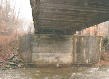
East Abutment
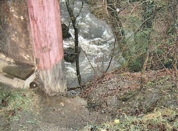
Southwest Corner of Bridge
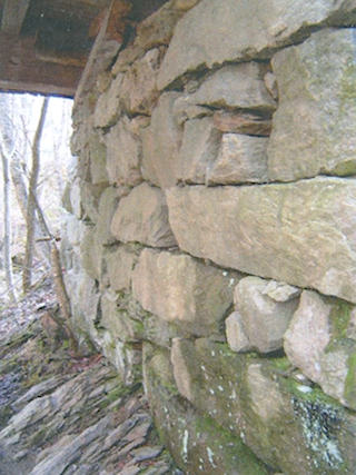
West Abutment
8. BRIDGE APPROACHES
Both bridge approaches are gravel and are in fair to good condition with steep grades beyond each end of the bridge. There is no guardrail installed at either end of the bridge. There are no bridge closed, vertical clearance signs, or weight limit signs posted within the immediate vicinity of the bridge with exception of one weight limit sign found on the ground near the east portal.
We recommend that each approach to the bridge be regraded and weathering steel guardrail be added to each corner of the bridge.
9. FIRE DETECTION/PROTECTION
There is no known fire protection system at the bridge. Three (3) fire detection/protection systems are generally used for covered bridges; fire retardant coating (NOCHAR/Poloseal), fire detection system (Protectowire) and a dry deluge sprinkler system.
A fire-retardant coating, such as "NOCHAR" or "POLASEAL", can be used to protect the bridge from fire. This coating works by raising the flashpoint of the wood and therefore making it difficult to start a fire. The coating is available in colored and clear versions that are applied to the wood by brush or spray. The coating does not affect the strength of the wood.
If a fire is started, it is advantageous to notify the local fire department as soon as possible. The "Protectowire" system works by running a small wire through key locations in the bridge. If a rapid rise in temperature is detected or if a wire is cut, the system alerts the local mutual aid or fire department. This advanced warning can greatly reduce fire damage to a bridge and hopefully prevent the fire from making the bridge a total loss. A deluge sprinkler system is not recommended for this bridge since the span is relatively short and water can be directed to the center of the bridge from either end.
For the purposes of this study, we have assumed that the NOCHAR and POLASEAL will be used on the bridge. We have not included a protectowire system for the bridge based upon our previous experience with the Town of Montgomery; however, we recommend the option of installing it be presented to the Town. The estimated cost of installing a protectowire system is $15,000 - $20,000 since there is no power source near the bridge. We recommend that the Town, specifically the fire chief, make the final decision on which systems should be used on this bridge.
10. LIGHTING/UTILITIES
There is no lighting present on the bridge or at the immediate approaches. Lighting can be an effective means to deter vandalism and improve visibility at night. The decision to add lighting to the bridge should be made by the Town. For this study, the cost of adding interior lighting to the bridge has not been included in the cost estimate in Appendix B.
11. TRAFFIC CONTROL
The Hutchins Covered Bridge serves a single residence at the end of a dead end road. We understand that the resident may only reside in the house on a seasonal basis. If so, consideration should be given to scheduling construction of the project when they are away assuming provisions for fire fighting are made. We have assumed for this study that access to this residence during construction will be required.
Two (2) traffic control options were considered for this study;
- installation of a temporary bridge to the south of the bridge
- upgrading TH 27 (Class 4 road)
Temporary construction easements were obtained for Option 1 on December 27, 2001. Each option is discussed in more detail in the following paragraphs.
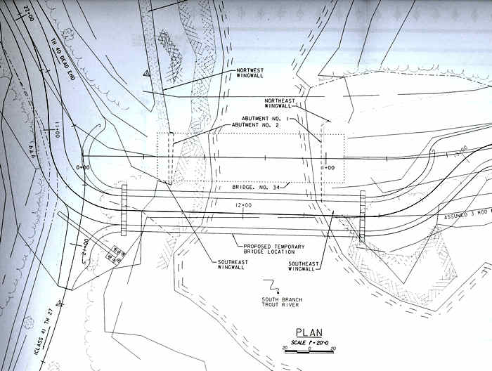
Proposed Location of Temporary Bridge
Option A includes minor clearing, temporary fill and installation of a temporary bridge and guardrail directly south of the existing bridge. As discussed above, temporary easements have been obtained by VTrans outside the assumed 3-rod right-of-way. The proposed location of the temporary bridge is in Figure 1 in Appendix C.
VTrans prepared a cost estimate dated February 24, 2005 of $146,777.66 for the temporary bridge and associated site work. This estimate appears reasonable with the exception of the one-way temporary bridge cost of $125,000.00. Due to recent flooding in VT, NH and ME the cost of temporary bridges has increased with increased demand. We estimate this cost today to be $160,000.00. Adjusting this item and increasing the estimate for inflation, we estimate the total cost of Option A to be $185,000.00.
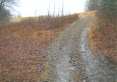
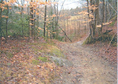
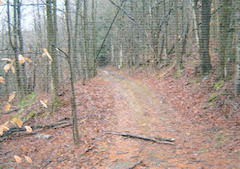
Option B includes upgrades to approximately 1,800' of TH 27 (Class 4 road) from the west end of the bridge to Gibou Road. TH 27 is an unimproved gravel road approximately 8' wide. The road grade varies but is approximately 25% in one location. The Vermont State Design Standards require the following minimum requirements for Local Roads and Streets assuming and ADT of 0-25 cars and design speed of 25 mph:
- 7' wide lanes, 0' shoulder (14' wide for two (2) lanes)
- Stopping sight distance = 150'
- Corner sight distance = 275'
- Maximum grade = 15% for mountainous and 11 % for rolling terrain
A great deal of work will be required to upgrade TH 27 to meet the State Standards above. Since the road is terraced into the side of a hill in most locations, extensive retaining walls with guardrail will be required to widen the road. In addition, tree clearing and ledge removal will be required in some locations. Hartgen Archaeological Associates (HAA) reviewed TH 27 for potential impacts (see Section 12), which also must be considered. The estimated cost to upgrade TH 27 as a detour route is $315,000. Please note that this is a conceptual estimate and ground survey would be required for a more detailed estimate.
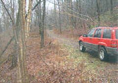
North End of TH 27
Steep Slope Near Field Along TH 27
TH 27 Near Gibou Rd
TH27
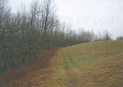
TH 27 Through Field
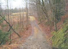
TH 27 at Gibou Rd.
12. ARCHEOLOGICAL RESOURCE ASSESSMENT
Bridqe Vicinity
VTrans conducted an Archeological Field Review at the areas immediately adjacent to the bridge (See Appendix E). The purpose of the review was to determine any potential impacts the project may have. The review identified the remains of a former tub factory at the northwest corner of the bridge and concluded there were no other areas of concern due to the steep slopes on the other three (3) corners of the bridge. The results were presented at the December 2, 1998 DHP meeting and it was agreed that a temporary one-way bridge south of the existing bridge would not effect any significant archeological properties.
TH 27 Detour Route
HT A retained HAA to perform an Archeological Resource Assessment (ARA) along the TH 27 Detour Route. A complete copy of their report is included in Appendix E. HAA subdivided the detour route into four (4) areas with Area 1 being closest to the bridge and Area 4 being the southernmost area.
In summary, HAA concluded the following:
- Area 1 - A fieldstone foundation and cellar hole were located. HAA recommends that area be cordoned off and the area between it and the detour be studied further.
- Area 2 - Archeological shovel testing is recommended.
- Area 3 - Archeological shovel testing is recommended.
- Area 4 - Archeological shovel testing is recommended at a small terrace area.
13. ESTIMATE OF COST
An estimate of cost was prepared for this project using the "Estimator" software and past HT A and VTrans covered bridge bid data for a six (6) ton live load limit and a temporary bridge structure. The estimate of cost is included in Appendix B and includes the following major items:
Six (6) Ton Live Load
- Remove and replace deteriorated bridge members including:
- Crossbeams
- Truss chord members
- Floor beams (all) and decking (all)
- Siding
- Bed timbers
- Knee braces
- Install new timber curb in the bridge.
- Realign the bridge trusses to eliminate rack in the trusses.
- Repair the west abutment (crack sealing, waterproofing and add weep holes).
- Reconstruct the west abutment breastwall.
- Install a new stone wingwall extension at the southeast corner of the bridge.
- Install concrete backwalls at each abutment.
- Apply fire retardant coating and fungicide to the bridge.
- Install a temporary detour bridge to the south of the existing bridge.
- Install weathering steel guardrail at the four (4) corners of the bridge.
- Regrade 50' of approach pavement at each end of the bridge.
The total estimated cost of all recommended work items is approximately $578,025.00 including 5% for contingences. A complete breakdown of this estimate is included in Appendix B.
Twentv (20) Ton Live Load
- All items included under the six (6) ton live load option.
- Install new concrete abutments in front of the existing abutments to support longitudinal stringers.
- Install longitudinal glulam stringers beneath the bridge.
- Additional upgrades to the bridge trusses.
- Upgrade floorbeams and decking to glulam.
The total estimated cost of all recommended work items is approximately $777,525.00 including 5% for contingences. A complete breakdown of this estimate is included in Appendix B.
14. CONCLUSIONS
Hoyle, Tanner & Associates, Inc. (HTA) has been assigned, through a retainer contract with the Vermont Agency of Transportation (VTrans), the task of preparing an Engineering Study for the rehabilitation of the Hutchins Covered Bridge. Rehabilitation of the bridge for a six (6) ton and twenty (20) ton live load capacity were studied. The project's Priority of Uses as defined by the Historic Covered Bridge Preservation plan is "Special Use on Roads" if a six (6) ton live load is pursued and "Limited Use on Roads" if a twenty (20) ton live load is pursued.
The Hutchins Covered Bridge was inspected and load rated to determine it's current condition. Our rating assumes replacement of deteriorated bridge members. It was determined that at the inventory stress limit the existing trusses have a live load capacity of approximately H7.8 (7.8 tons), the floor beams have a capacity of H4.2 (4.2 tons), and the deck has a capacity of H7.2 (7.2 tons).
An option was investigated to increase the live load capacity of the bridge to twenty (20) tons. Since the trusses are unable to support twenty (20) tons, glulam stringers, floorbeams and decking would be required.
Two (2) detour options were evaluated for the project A) installation of a temporary bridge to the south of the bridge and B) upgrading TH 27 (Class 4 road). The estimated cost of Option A is $185,000.00, while option B is $315,000.00. The much higher cost of Option B is due to its length (1,800') and location (terraced into a hill). The geometry of the hill location necessitates a large amount of fill and retaining walls to meet state standards. Option A is recommended due to its lower cost and much smaller environmental impact.
The total estimated cost of all recommended work items utilizing a temporary detour bridge and six (6) ton live load limit is approximately $578,025.00 including contingencies. The total estimated cost of all recommended work items utilizing a temporary detour bridge and twenty (20) ton live load limit is approximately $777,525.00 including contingencies.
Appendices
APPENDIX A - Wood Species ID Report
Memorandum
Date: January 25, 2006
To: Sean James, P.E.
Project Manager
Hoyle, Tanner & Associates
150 Dow Street
Manchester, NH 03101
From: Doug Gardner
Professor of Wood Science
AEWC Center
Subject: Identification of 15 bridge timber wood samples from Bath Village Covered Bridge, E. Fairfield Covered Bridge and Hectorville Covered Bridge.
Following are my findings relative to the identification of the bridge timber wood species samples you sent to me on January 20,2006. I relied on my background in wood identification, and the Key to Gross Identification found in the Textbook of Wood Technology, 4th Edition by Panshin and De Zeeuw (ISBN 0-07-048441-4) in making my evaluations. Identification of the wood samples was made using a 10x hand lens.
Samples Identified
A summary of the wood species identified are listed in Table 1 along with comments related to the nature of the samples. More details about each sample are described below.
Table 1. Summary of wood species identified comprising wooden bridge members
| Sample Label | Wood Species | Comments |
| Hutchins C B Deck | Eastern hemlock | |
| Hutchins C B Chord | Eastern hemlock | Cubical brown rot decay |
| Hutchins C B Trunnel | Hard Maple | Insect attack (holes) |
| Hutchins C B Lattice | Spruce | |
| East Fairfield C B Floor Beam | Fir/Hemlock | Superficial insect attack |
| East Fairfield C B Deck | Eastern Hemlock | Brittle |
| East Fairfield C B Rafter | Spruce/Fir | Slow growth> 40 rings per 1/2 inch |
| East Fairfield C B Chord | Spruce | |
| East Fairfield C B Stringer | Eastern Hemlock | |
| Bath Village Bridge -Old Floor Beam | Eastern Hemlock | |
| Bath Village Bridge - Diagonal | Spruce | Creosote Treated |
| Bath Village Bridge - Deck | Spruce | |
| Bath Village Bridge - Chord | Spruce/Fir | Creosote Treated |
| Bath Village Bridge - Trunnel | White Oak | |
| Bath Village Bridge - New Floor Beam | Hemlock | Creosote Treated |
Wood species in italics are best estimations based on nature of samples.
- Hutchins C B Deck: Eastern Hemlock (Tsuga canadensis): wood tended to be brittle and exhibited an abrupt transition from earlywood to latewood in the growth increments.
- Hutchins C B Chord: Eastern Hemlock (Tsuga canadensis): wood tended to be brittle and exhibited an abrupt transition from earlywood to latewood in the growth increments. Sample also exhibited signs of cubical brown rot wood decay.
- Hutchins C B Trunnel: Hard Maple (Acer saccharinum): wood was diffuse porous hardwood. Outer margin of growth ring was dark brown in color. Wood had some signs of insect attack (holes 1/16th inch in diameter). Possibly powder post beetle attack.
- Hutchins C B Lattice Spruce (Picea spp.). wood yellowish-white-brown and contains resin canals, exhibits a gradual transition between the earlywood and latewood in the growth increment.
- East Fairfield C B Floor Beam: Either Eastern Hemlock (Tsuga canadensis) or Fir (Abies spp.): wood did not contain resin canals and the transition from earlywood to latewood tended to be semi abrupt which is characteristic of both species.
- East Fairfield C B Deck: Eastern Hemlock (Tsuga canadensis): wood tended to be brittle and exhibited an abrupt transition from earlywood to latewood in the growth increments.
- East Fairfield C B Rafter: Either Spruce (Picea spp.) or Fir (Abies spp.): the slow growth of this sample (greater than 40 rings per 12 inch) precluded positive identification. The transition from earlywood to latewood appeared to be gradual and this is a characteristic of both species.
- East Fairfield C B Chord: Spruce (Picea spp.). wood yellowish-white-brown and contains resin canals, exhibits a gradual transition between the earlywood and latewood in the growth increment.
- East Fairfield C B Stringer: Eastern Hemlock (Tsuga canadensis): wood tended to be brittle and exhibited an abrupt transition from earlywood to latewood in the growth increments.
- Bath Village Bridge - Old Floor Beam: Eastern Hemlock (Tsuga canadensis): wood tended to be brittle and exhibited an abrupt transition from earlywood to latewood in the growth increments.
- Bath Village Bridge - Diagonal: Spruce (Picea spp.). wood contains resin canals, exhibits a gradual transition between the earlywood and latewood in the growth increment. Sample was treated with creosote.
- Bath Village Bridge - Deck: Spruce (Picea spp.). wood yellowish-white-brown and contains resin canals, exhibits a gradual transition between the earlywood and latewood in the growth increment.
- Bath Village Bridge - Chord: Either Spruce (Picea spp.) or Fir (Abies spp.): This sample was creosote treated and the small sample size precluded positive identification. The transition from earlywood to latewood appeared to be gradual and this is a characteristic of both species.
- Bath Village Bridge - Trunnel: White Oak (Quercus spp.): Ring porous hardwood with the earlywood vessels containing tyloses.
- Bath Village Bridge - New Floor Beam: Most likely Eastern Hemlock (Tsuga canadensis): wood tended to be brittle and exhibited an abrupt transition from earlywood to latewood in the growth increments. This sample was completely saturated with creosote which precluded positive identification.
My consulting fee is $50 per sample, so the cost for this wood sample identification is $750.00. Payment can be made to:
Douglas J. Gardner
484 Day Road
Brewer, ME 04412
APPENDIX B - Estimate of Cost
Estimate
Estimated Cost: $550,500.00
Contingency: 5.00%
Estimated Total: $578,025.00
Hutchins Covered Bridge, Montgomery, VT - Montgomery BHO 1448(23) Bridge No. 34,
Town Highway No. 27
Letting Date: 08/01/06
Spec Year: 01
Unit System: E
Work Type: COVERED BRIDGE REHABILITATION
Highway Type: LOCAL
Urban/Rural Type: RURAL
Season: CONSTRUCTION SEASON BIDS (4/15 - 10/15)
County: FRANKLIN COUNTY
Prepared by HTA on 07/31/06
Group 0001: Roadway
| Line # Item Number | Quantity | Units | Unit Price | Extension |
| 0005 201.10 Clearing and Grubbing | 1000 | LS | $2,000.00 | $2,000.00 |
| 0025 301.26 Subbase of crushed gravel | 25.000 | CY | $50.00 | $1,250.00 |
| 0160 608.25 All Purpose Excavator Rental, Type 1 | 5.000 | HR | $75.00 | $375.00 |
| 0185 635.10 Mobilization | 1.000 | LS | $33,005.00 | $33,005.00 |
| 0190 649.51 Geotextile for silt Fence | 150.000 | SY | $8.00 | $1,200.00 |
| 0192 888.90 Haybales for erosion control | 100.00 | Each | $7.00 | $700.00 |
| 0195 888.90 Temporary Detour Bridge | 1.000 | LS | $185,000.00 | $185,000.00 |
Total for Group 0001: $223,530.00
Group 0002: Superstructure
| Line # Item Number | Quantity | Units | Unit Price | Extension |
| 0250 204.25 Structure Excavation | 20.000 | CY | $30.00 | $600.00 |
| 0252 204.30 Granular Backfill for structures | 20.000 | CY | $50.00 | $1000.00 |
| 0260 501.25 Concrete, Class B | 10.000 | CY | $750.00 | $7,500.00 |
| 0265 502.10 Shoring Superstructure | 1.000 | LS | $70,000.00 | $70,000.00 |
| 0275 507.16 Drilling and grouting dowels | 90.000 | LF | $20.00 | $1,800.00 |
| 0276 507.17 Epoxy coated reinforcing steel | 1,500.000 | LB | $4.00 | $6,000.00 |
| 0277 513.30 Strucural Painting | 1.000 | LS | $25,000.00 | $25,000.00 |
| 0290 513.36 Containment & Environmental Protection Field | 1.000 | LS | $7,500.00 | $75,000.00 |
| 0295 514.10 Water Repellent | 30.000 | GAL | $50.00 | $1,500.00 |
| 0310 522.20 Structural Lumber and Timber - Untreated (Top Lateral Cross Bracing) | 0.300 | MFBM | $15,000.00 | $4,500.00 |
| 315 522.20 Structural Lumber and Timber - Untreated (Bed Timbers) | 0.500 | MFBM | $7000.00 | $3,500.00 |
| 325 522.20 Structural Lumber and Timber - Untreated (Floorbeams) | 3.700 | MFBM | $9,000 | $33,300.00 |
| 327 522.20 Structural Lumber and Timber - Untreated (Truss Chord) | 2.000 | MFBM | $18,000.00 | $39,000.00 |
| 330 522.20 Structural Lumber and Timber - Untreated (Truss Lattice) | 0.900 | MFBM | $14,000.00 | $12,600.00 |
| 335 522.20 Structural Lumber and Timber - Untreated (Siding Supports) | 0.150 | MFBM | $7000.00 | $1,050.00 |
| 340 522.20 Structural Lumber and Timber - Untreated (Miscellaneous Repairs) | 1.000 | LS | $12,500.00 | $12,500.00 |
| 345 522.25 Structural Lumber and Timber - Untreated (Sawn Decking) | 5.800 | MFBM | $7,000.00 | $40,600.00 |
| 350 522.25 Structural Lumber and Timber - Untreated (Wood Curbing) | 1.100 | MFBM | $7,000.00 | $7,700.00 |
| 355 522.30 Structural Lumber and Timber - Untreated (Siding) | 1.800 | MFBM | $6,000.00 | $10,800.00 |
| 360 522.20 Partial Removal of Structure | 1.000 | LS | $10,000.00 | $10,000.00 |
| 0361 580.14 Repair of Concrete Substructure Surface Class II | 2.000 | SY | $700.00 | $1,400.00 |
| 0365 580.18 Overhead and Verticle Concrete Repair Material | 2.000 | CF | $700.00 | $1,400.00 |
| 0370 602.20 Dry Rubble Masonry | 1.000 | LS | $6,600.00 | $6,600.00 |
| 0415 675.20 Traffic Signs, Type A | 62.000 | SF | $10.00 | $620.00 |
Total for Group 0002: $303,470.00
Group 0003: Full Construction Engineering Items
| Line # Item Number | Quantity | Units | Unit Price | Extension |
| 380 621.90 Temporary Traffic Barrier | 30.000 | LF | $50.00 | $1,500.00 |
| 0385 631.10 Field Office-Engineers | 1.000 | LS | $20,000.00 | $20,000.00 |
| 0395 631.16 Testing Equipment - Concrete | 1.000 | LS | $2,000.00 | $2,000.00 |
Total for Group 0003: $23,500.00
Estimate - Temporary Bridge
Estimated Cost: $315,000.00
Contingency: 0.00%
Estimated Total: $315,000.00
Temporary Detour, Hutchins Covered Bridge, Montgomery, VT - Montgomery BHO 1448(23) Bridge No. 34,
Town Highway No. 27
Letting Date: 08/01/06
Spec Year: 01
Unit System: E
Work Type: COVERED BRIDGE REHABILITATION
Highway Type: LOCAL
Urban/Rural Type: RURAL
Season: CONSTRUCTION SEASON BIDS (4/15 - 10/15)
County: FRANKLIN COUNTY
Prepared by HTA on 07/31/06
Group 0001: Roadway
| Line # Item Number | Quantity | Units | Unit Price | Extension |
| 0005 201.10 Clearing and Grubbing | 1.000 | LS | $20,000.00 | $20,000.00 |
| 0015 203.15 Common Excavation | 500.000 | CY | $10.00 | $5,000.00 |
| 0020 203.35 Gravel Backfill for Slope Stabilization | 3,100.000 | CY | $15.00 | $46,500.00 |
| 0022 204.20 Trench Excavation of Earth | 70.000 | CY | $20.00 | $1,400.00 |
| 0023 205.10 Drilling and Blasting of Solid Rock | 100.000 | LF | $100.00 | $10,000.00 |
| 0025 301.15 Subbase of Gravel | 500.000 | CY | $15.00 | $7,500.00 |
| 0092 401.10 Aggregate Surface Course | 500.000 | CY | $20.00 | $10,000.00 |
| 0126 601.0025 24" CSP .064(2-2/3 x 1/2) | 120.000 | LF | $20.00 | $2,400.00 |
| 0143 605.10 6" Underdrain | 500.000 | LF | $20.00 | $10,000.00 |
| 0160 621.21 Heavy Duty Steel Beam Guard Rail | 600.000 | LF | $25.00 | $15,000.00 |
| 0185 635.10 Mobilization | 1.000 | LS | $22,880.00 | $22,880.00 |
| 0190 649.51 Geotextile For Silt Fence | 600.000 | SY | $8.00 | $4,800.00 |
| 0192 651.10 Haybales For Erosion Control | 340.000 | EACH | $8.00 | $2,720.00 |
| 0193 651.15 Seed | 120.000 | LB | $10.00 | $1,200.00 |
| 0194 651.18 Fertilizer | 100.000 | LB | $10.00 | $1,000.00 |
| 0194 651.35 Topsoil | 100.000 | CY | $50.00 | $5,000.00 |
Total for Group 0001: $165,400.00
Group 0002: Superstructure
| Line # Item Number | Quantity | Units | Unit Price | Extension |
| 0361 526.30 MECHANICALLY STABILIZED EARTH (MSE) WALL | 528.571 | SY | $252.00 | $133,199.89 |
Total for Group 0002: $133,199.89
Group 0003: Full Construction Engineering Items
| Line # Item Number | Quantity | Units | Unit Price | Extension |
| 0380 652.10 EROSION PREVENTION & SEDIMENT CONTROL PLAN | 1.000 | LS | $5,000.11 | $5,000.11 |
| 0381 652.20 M0NITORING EROSION PREVENTION & SEDIMENT CONTROL PLAN | 100.000 | HR | $64.00 | $6,400.00 |
| 0382 652.20 MAINTENANCE OF EROSION PREVENTION & SEDIMENT CONTROL PLAN | 1.000 | LS | $5,000.00 | $5,000.00 |
Total for Group 0003: $16,400.11
APPENDIX C - Plan, Truss, and Cross Section Drawings
Plan View of Existing Conditions
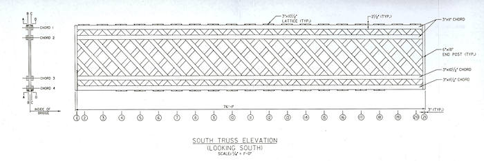
South Truss
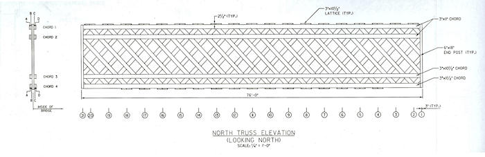
North Truss
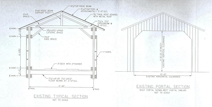
Typical and Portal Section
APPENDIX D - VTrans Preliminary Hydraulic Study
VT AGENCY OF TRANSPORTATION PROGRAM DEVELOPMENT DIVISION
HYDRAULICS UNIT
TO: John Weaver, Structures Project Manager
FROM: Nick Wark, Civil Engineer III
DATE: May 25,2005
SUBJECT: Montgomery BHO 1448(23) TH27, Br34
The above listed project is a covered bridge rehabilitation. The bridge spans the South Branch of the Trout River. The existing bridge has approximately 11' of freeboard over Q100, so hydraulic capacity is not an issue at this site.
If needed, a temporary structure should be selected to best fit the alignment of the river and roadway. Just upstream of the existing bridge is a bend in the river. In order to span the channel upstream, the temporary structure should have a minimum span of 100'. Downstream of the existing bridge the channel has very steep banks consisting mostly of ledge. In order to span the channel downstream we suggest that a temporary bridge have a span of at least 85'. Shorter spans could be used; however we feel that placing temporary abutments on the steep ledge would be more costly than using a longer span.
Please contact us if you have any questions or if we may be of further assistance.
NJW
cc: Hydraulics Project File via MJT
Hydrauhcs Chrono File